The interface between the Clearcom intercom bus and the Sony CCUs consists simply of a capacitor and transformer, and the connectors necessary to plug into the other equipment.
The intercom bus connection is made with a male and female 3-pin XLR connector. This allows the interface unit to be plugged into the intercom bus at any point just like any other intercom unit. Note that no connection is made to the power line as this interface is passive.
The capacitor provides DC-blocking to keep the intercom "call" signal out of the transformer windings. The transformer converts the unbalanced intercom audio signal to the balanced audio signal used by the Sony CCUs.
This is also the point where the tally signal from the video switcher is connected to the CCUs. The tally indicators on the CCU and on the camera are activated by pulling the CCU's tally line to tally ground. This can be done with a relay contact, switch, or a transistor.
The connectors to the Sony CCUs are 4-pin DIN connectors and carry both the intercom and the tally signals to all the cameras.
Pinouts:
Intercom Bus
CCU Bus
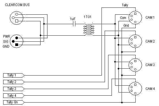
Schematic Diagram